Saturday 20 April 2024

Allinaire Korg PS3200 (PS3300 Emulation MAM RS3 Res) MS50 MS20 MS10 VC10...

..

As a huge Korg fan I got to put together an Ensemble piece using 1978 era Korg Synths. The hero is the mighty PS3200 polyphonic synth playing homage to its big brother (and, as of 2024, soon to be re-released by Korg, the PS3300) by using the direct out of the 3200 into a MAM RS3 Resonator which recreates the famous PS3300 & 3100 modulated resonator circuit. The 3200 plays pads, base and noises. 
Lead lines and extra pads via an MS20 into a VC10 Vocoder combo give a haunting breathy sound. 
The SQ10 Sequencer drives the MS50 and MS20 synths for a rhythmic sequence and the MS10 with its famous pulse width modulation provides additional baselines. 
Effects include the SE500 Tape Echo and the more modern Kaos Pad Mini. 
All recorded on a Zoom R24 recorder. 
Percussion utilises some sounds sampled from the various Korg Synths and is added in Ableton Live. 

Recorded in April 2024, Wollongong courtesy of Jondent, with some additional sounds from my own original MS20 in Sydney. 

The Video is mixed together bits of footage from the session but missed most of the playing and modulation action - but still it’s always nice to see some vintage Korg gear in action! 

Additional notes: Some subtle detuning of the PS3200 individual notes was made possible via the Temperament Adjust mini pots. The PS3010 keyboard also provides for some interesting modulation effects via the joystick and the unique note triggering control. A Korg 3100 in the same studio verified the RS3 Resonator accuracy and the RS3 unit also is CV controllable like on the 3300. By using it with the PS3200 (which has 2 oscillators per note) it gets close to the functionality of a PS3300 but of course misses the fact that the 3300 has 3 Oscillators and 3 resonators etc. I look forward to the new PS3300FS announced by Korg at NAMM 2024.

Monday 8 April 2024

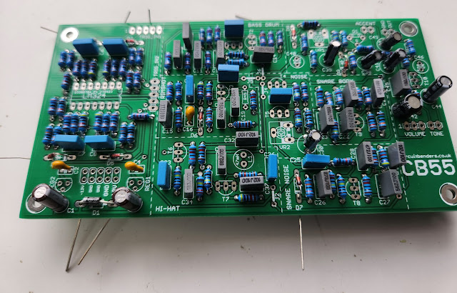
Circuitbenders CB55 - drum machine build notes.

These are my build notes for the circuit benders clone of the Roland/- Boss Dr 55 drum.
The clone is called the CB-55.
The original is a really simple and great sounding machine. It's definitely a classic.
I think where it falls short is it's limited sequencer, and that its tricky to sync to external gear. 
I loved the first DR-55 I bought so much, that I purchased a second one with the intention to mod it.
But I just couldn't vandalize  it .
Mods to overcome this are out there but I think its a shame to need to mod vintage gear. 
These relics are getting harder to find as the years go by and in the future, the ones that will
retain their value will be those in original condition.

So from a practical level, get an original to admire & treasure and build the clone to 
mod to your hearts content.


Links:


I'll install the trigger conditioning circuit.... connected to TRIG_IN1 connector.
This allows you to connect 5V triggers that last longer than 10ms


The build looks easy. all through hole with standard parts that i probably already have in my store.


Resistors first.

Caps 


fairly straight forward build so far.

D1 1N4001 Rectifier diode
D2, D3, D4, D5, D6, D7, D8, D9 1N4148 or 1N914
D1 is a larger 1N4001
rectifier diode that provides polarity protection for the power input, but all the others can be general purpose
small signal diodes such as 1N4148's or 1N914'


Jumper wires:
The jumper wires at J3-J7 connect the output of each voice circuit to the main mix bus.
These links are designed as 
jumpers for easy mods to provide individual outputs, but at this point it would probably be better to just install 
them. You can always change things at a later date.


the voltage regulators and transistors. 

REG1 is a 78L06 regulator that supplies the 6v power to the 
voice circuits. REG2 is a 78L09 that supplies 9v to the trigger conditioning circuit
ebay ... ordered


There is just one IC
IC1 - LM324 Quad opamp


T1, T2, T3, T4, T5, T6, T7, T8, T9, T10 2SC945 Or similar transistor
Its a  Bipolar (BJT)


Wednesday 13 March 2024

NLC - LDRama - build notes

 These are my build notes for the nonlinear circuits LDRama module.
tHIS eurorack 28HP light sensor module  was designed upon suggestions from Alex Brunori. 
The idea is to play a video (or skype or whatever is the newest thing) fullscreen on your phone and place the phone on the LDR array. The module will generate CVs in response to what is happening in your video.

I've got a Arduino controlled LED project in the works, and I'd like to see if I can do something interesting with the two.

links
+ BOM

I think this is a pretty neat idea.
It is designed to suit a typical 5x2 inch screen, larger screens work fine tho some info around the edges is lost. Ideally the module will sit flat, if on an angle patch-cords into the top row of jacks hold it up very nicely


You can also patch in an external signal, such as a CV from a sequencer, and process this thru the LDRs.


The BOM suggests using GL12528 LDRs x 48


get the opamps on first.
TL072 x 15


resistors next.
lots of 1k and 100k


These 8 resistors marked 100k should all be 1k
The RL and 1k should be swapped
2k2 resistors for RL


I'm using a 10R resistor for reverse
voltage protection


The LDRs are larger than the usual
You need 48 x GL12528
on order from ebay

to be continued.....

-----------------------------------------------------------------------------------
You can find more NLC builds here.
--------------------------------------------------------------------------------------

Sunday 10 March 2024

NLC Stochaos - Build notes

These are my build notes for the nonlinear circuits "stochaos" module.
It's a 8hp eurorack.


STOCHAOS...... It's a random rhythm pattern generator or sequencer which produces gates and control voltages 


There are just two inputs ; IN & RST
Everything else is an output


Links


This is a decent sized build using 2 PCBs
Start with the ICs and transistors.

The module uses a lot of cmos
CD4070  x2....... XOR
CD4040 x2  .... clock divider 


CD4040 clock divider's outputs feed the four binary inputs of a CD4028 BCD to Decimal converting chip, creating pseudo-random sequences, depending on different CD4040 outputs feeding different CD4028 BCD inputs.


"The circuit can be easily modified by replacing the two 4070 XOR chips with two 4081 AND chips (or any other 4 channel two input logic chip – OR, NAND, XNOR, NOR). I might Build both versions ....the one-gate-at-a-time version tends to get a much faster clock signal" (Andrew F). 


CD 40175... Quad D-type Flip-Flop


CD 4028....... BCD-to-decimal Decoder


Resistors

Pink noise level :
*** 1M-10M? x 1 ........................select for pink noise level .
................ im using a 10M

RL (LED resistor)  x 9 ..............select resistor to suit LED
brightness (prob 4k7 to 10k) ..... im using 4.7K


....
power rectifier BAT54GWX


Diodes
LL4148

5mm LED for chaos circuit on top PCB, any
crappy LED is fine but high V-on is
good so a blue one if you have it.

headers to unite the two PCBs


switch

SPDT - 
on-off-on


Jacks

3mm LEDs x 8 ....Up to you, diffused lens are easier
on the eyes. Square hole = anode 


I always do these last.

You're there


First tests.
The LEDs light up. That's promising.


the input needs a SAW or SQUARE wave 
Sine & Tri waves don't trigger the module very well.

-----------------------------------------------------------------------------------
You can find more NLC builds here.
--------------------------------------------------------------------------------------

Saturday 2 March 2024

CMOSC - Drone Oscillator - Build notes - Nonlinear Circuits

These are my build notes for the Nonlinear Circuits CMOSC module
Its a eurorack format module.

CMOSC is an updated version of the 
4U CMOSC (CMOS drone Oscillator). 

Each module has 6 oscillators; the frequency of each
oscillator can be set with the pots. Feeding a signal to 
input will decide which oscillator signal will appear at the output. If the signal is low, oscillator A is heard, if the 
signal is high oscillator B is heard. 
This module gets very interesting when the outputs of each oscillator pair are fed into other pairs, which are themselves controlled by others and so on…..complex, evolving drones. Put
patchcords into every jack so every pair is controlled by another pair, listen to one of the outputs, twiddle the knobs until you feel satisfied.
The sync input actually disables the oscillators, the unmarked output is a sync output…or if you like; it goes high when the oscillators are disabled. It is most interesting to put an audio signal into the sync input, preferably from the other CMOSC module


The Eurorack CMOSC also  consists of 6 oscillators. 

each can be switched between two frequencies set by a single pot. When the pot is in the mid-point the two frequencies are about the same. Turn the pot to min or max to switch between higher and lower frequencies, or lower and higher. 


It's a gated oscillator.
Meaning  Each oscillator controls the switching of its subsequent neighbour
 (1-2, 2-3, 3-4, 4-5, 5-6, 6-1) via the switching pins of the input jacks. 
Patching in a signal will break this cacophony and allow you to have some control over proceedings.

Links
+ BOM


No hard to find parts


A single atom deprived of vibration could wreck the universe.
William Walker Atkinson

---------------------------------------------------

"there's only so much you can do with a op amp "... Paul S

CD40106 1 soic Mouser: 595-CD40106BM96 or 771-HEF40106BTD-T


CD4053 2 soic Mouser Part No: 595-CD4053BM96 or 771-HEF4053BTD-T


TL074 or TL084 2 Soic Tayda: A-1140 or A-1137


LL4148 x 7 sod-80 Tayda: A-1213
BC847 x6 SOT23-3 Tayda: A-1339 
Resistors: 1k, 10k, 100k, 220K


The two 5V1 Zeners (SOD80) are optional..... I'm leaving them off for now.
The function of these 2 zeners is to keep the output of the summed stage to 
exact Eurorack …ahem…‘standards’.
The individual outputs generally swing between +/-5V (so 10Vp-p) anyway, which is pretty much
within the "standard range so I don't think I'll need them.
(The pads for the 5V1 zeners are there if I change my mind).
The summed out is very noisy and raw.

I'm using a 10R instead of the Schottky (for the rectifier).
Just don't plug the power supply in backwards. 

caps
C1-C6 set the frequency range for each oscillator. 470nF gets down
to approx. 15Hz, so is probably the highest value you want to use
(assuming you want to keep things in the audio range). 
Andrew says its OK to mix values or keep them all the same.
I've decided to use all 470nF. Ill see how this sounds, then might experiment later.

*** I started to experiment with these caps. Changed C1 , C2, C3, C4 to 220nf.
      the drone was more audible*****


The other caps are 10uf and 100nF


Soldering the headers that join the two PCBs.

Pots & jacks.


You're done 


-----------------------------------------------------------------------------------
You can find more NLC builds here.
--------------------------------------------------------------------------------------